Robotic End Effector (Critical Matter Group)
This was a project that I undertook while working at the Critical Matter Group in the MIT Media Lab throughout my freshman year. In short, it’s an end effector mounted on a UR20 robotic arm that is capable of automatically melt-spinning polymer fibers around objects. In short, the objectives were to:
- Repeatedly stretch PCL into fibers through a dual heatbed/nail setup
- Modulate the width of the stretched PCL
- Wrap the stretched fibers around an object It does this by closing and opening two crocodile “jaws” to create the fibrous strands, then rotating the entire jaw system around an object to wrap it. Hence, it got the nickname “Croc End Effector”
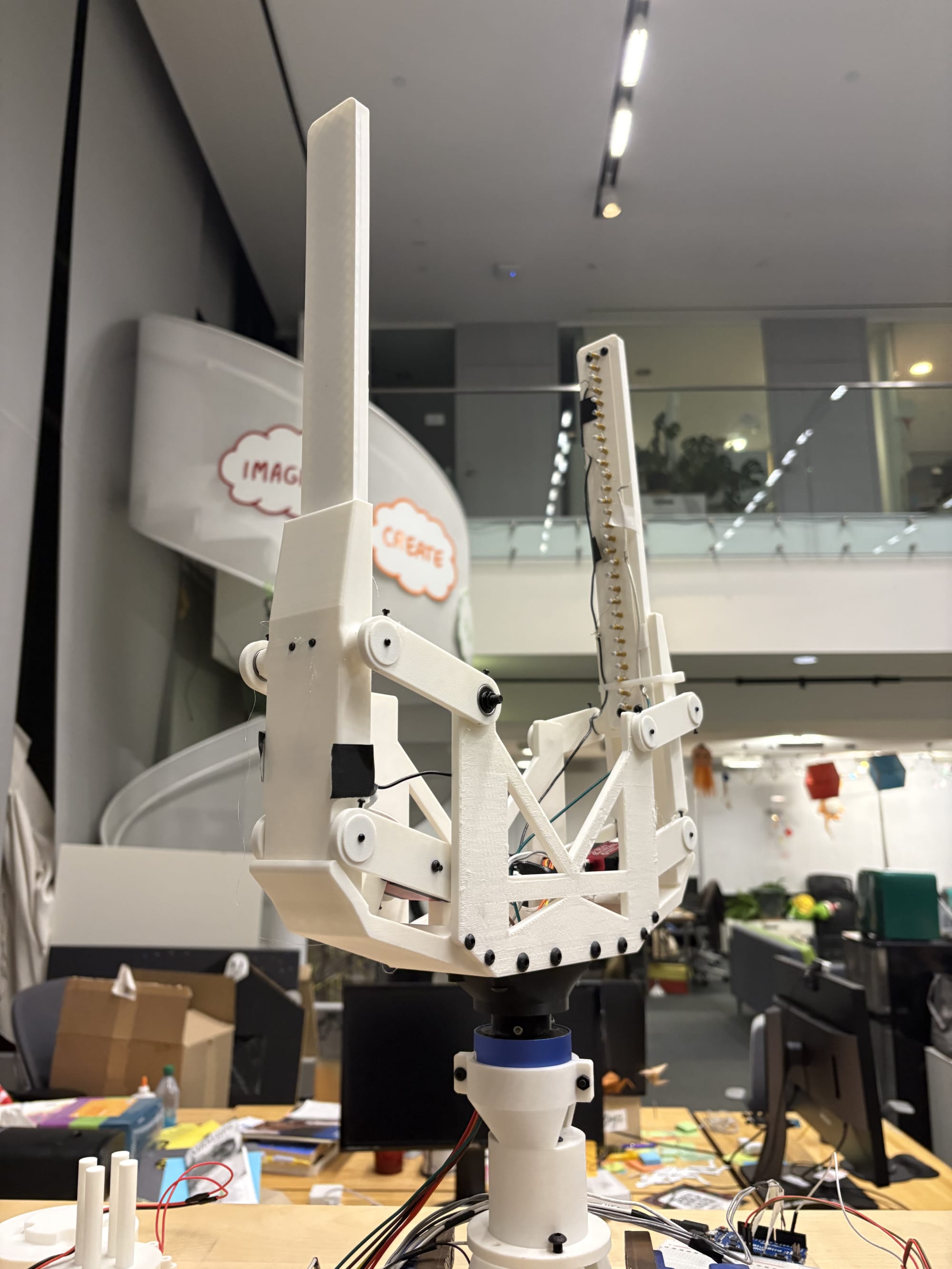 Croc End Effector
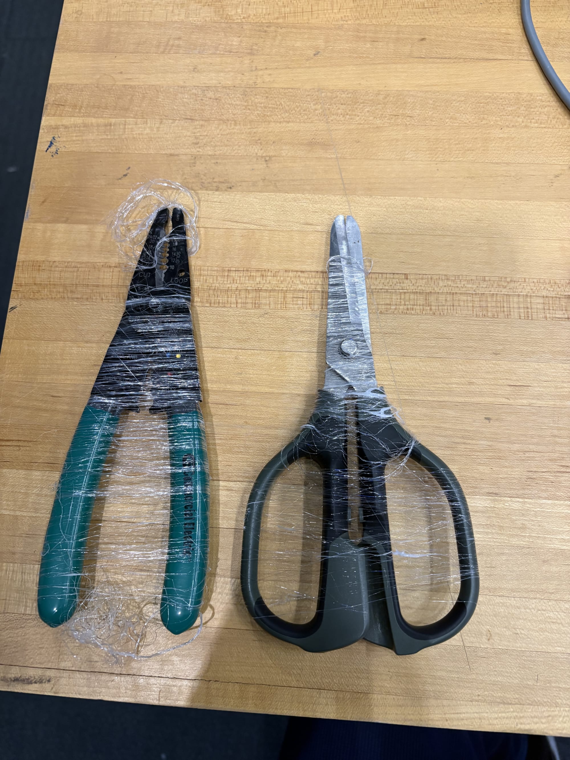 Melt-spun objects
This end effector underwent 5 iterations during the time I worked on it. In the earlier iterations, I was responsible for the entire system, from component selection, to CAD, to electronics design, to assembly. As more team members joined the project, I was able to focus more on the main frame design, system-level electronics, and assembly
The project can be broken up into 2 main pieces of hardware: a rotor (PCL system) and stator (houses motor that spins rotor)
The components of the rotor include:
- Heatbeds: The polymer we used for testing is PCL (polycaprolactone), which has a low melting point of around ~60C. We used ceramic heaters (the same kind in 3D printer nozzles!) mounted to an aluminum bed to hold the PCL, serving as the “jaws”. Each “jaw” served a different purpose:
- PCL Bed: This contained a heated, softened layer of PCL
- Nail Bed: This heated up a set of aluminum nails so that each would melt and pull away a fiber as the jaw opened
- Jaw Actuator: Reliably open and close the jaws
- Electrical System: Power regulation, communication to UR20 and remote station The components of the stator include:
- Rotation Motor: Be robust enough to spin a complex, heavy system
- Electrical System: Provide power and communication to an actively rotating device
Early Experimentations
In the earlier iterations of this project, I was responsible for all mechanical/electrical design, assembly, and testing.
Jaw Actuator
The challenge with this design was reliably closing the jaws with enough force to fully set the nails into the PCL bed, while being able to pull, but not break the fibers on release. In addition, because the entire system was rotating, it had to be symmetrical and lightweight.
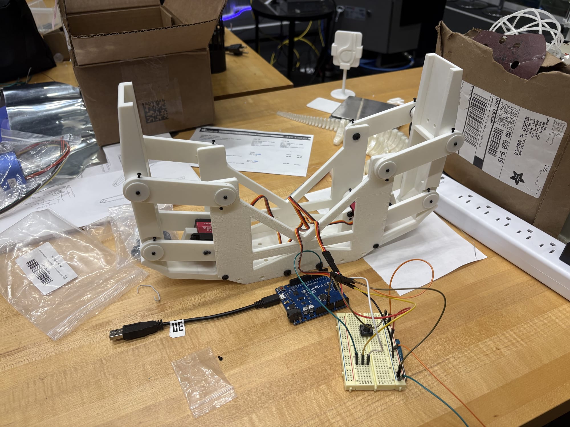
I experimented with several different designs, including a stepper-controlled lead screw that modulated a singular jaw (design and assembly done in a single week!). After this proved to be too slow, unstable, and unbalanced, I wanted to test a servo-driven 4-bar linkage mechanism.
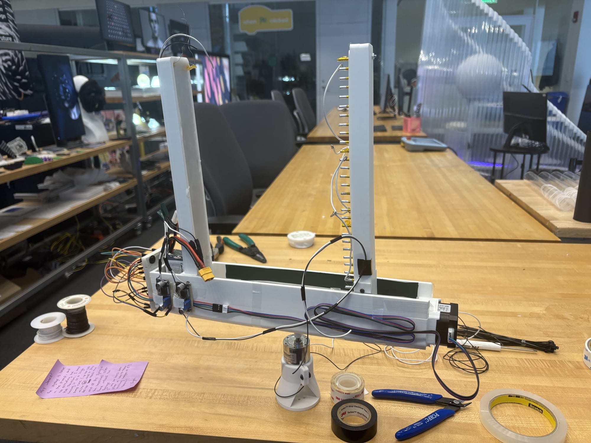 Lead screw initial design
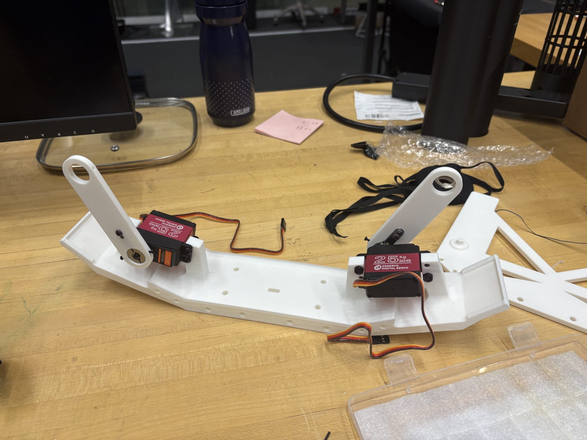
The concept behind the linkage design was driven by the realization that the jaws were only required to be level with each other, and that rotary motion was far simpler to implement than linear motion.
This design actually worked quite well, and was the first demonstration of an automatic melt-spinning system in the lab! However, it fell short in rigidity due to tolerances in the ball bearing integration design, and servos proved to be slightly underpowered in driving the heatbeds. Furthermore, one fatal flaw of this design was the change point of the linkage system, in which the linkages had a chance of collapsing on itself when they passed through their rotation point and became collinear.
Rotor Frame and Stator Design
The most important aspects of the frame are rigidity and symmetry. I centered my designs around these requirements.
My original design had the entire rotor system independently powered from its own battery, controlled wirelessly through an ESP32. While this worked in theory and would avoid dealing with wires between rotating systems, it proved to be impractical due to the high current draw of the heatbeds and the challenge of placing the battery in a symmetric way.
While iterating, I remembered this Tom Scott Video that introduced me to slip rings, and realized I could implement them into my design. Slip rings allow electrical signals to travel between a stationary base to a rotating structure, achieving this with metal “brushes” that glide across conductive rings as it spins.
The next iteration featured a slip ring that carried all power and communications through the stator and up to the rotor.
Heatbeds
Early iterations of the heatbeds used an array of PI heating elements that contacted the PCL directly. The nail bed is mounted to an aluminum plate, which is also heated up with PI heating elements.
Electrical System
As the components we used requested 5V, 6V, 9V, 12V, and 24V, I used buck converters to step-down voltages so each component got what they wanted. An Arduino connected to the stator commanded all motors and actuators, and I wrote a simple script to calibrate and send commands through USB Serial.
 Wrapping a pair of wire strippers
Sergio wrapping a model foot
Sergio wrapping his real foot
Later Iterations
As I progressed with the design of this end effector, a lot more progress was made in terms of reliability :). Yuxiang and Eleni also joined the Croc team, where they worked on the heatbeds and stator design.
Jaw Actuator
Because of their robustness, speed, and power, I switched to dual NEMA17 stepper motors driving 300mm SFU1204 ball screws, each controlling one jaw. To fix the rigidity issue from the previous lead screw design, I mounted each jaw on MGN9 linear rails that spanned the entire actuation range. This design proved to be incredibly robust, powerful, and precise enough for all jaw movements.
Rotor Frame Design
For ease of assembly, the first of my iterations with the dual ball screw design had the entire system mounted on a piece of laser-cut acrylic. But as the end effector grew in complexity, we decided to 3D-print the entire frame so all components could be seamlessly integrated.
Due to the size of the frame, it was impossible to print on a single printbed. We broke it up into 3 components (centerpiece and 2 rotationally symmetric side parts) that fit together with dovetails (thank you Yuxiang for the suggestion!)
Electrical System
While selecting components for this iteration, we were incredibly deliberate about voltages that each component requests, trying to simplify the power management system as much as possible. Ultimately, we ran all actuators and heatbeds at 24V, only using a single buck converter to bring it down to 6V for the microcontroller.
We used an Arduino Nano ESP32 that communicated to a controller using the ESP-NOW protocol.
I also implemented limit switches in these iterations so the stepper motors could be calibrated.
 Final CAD
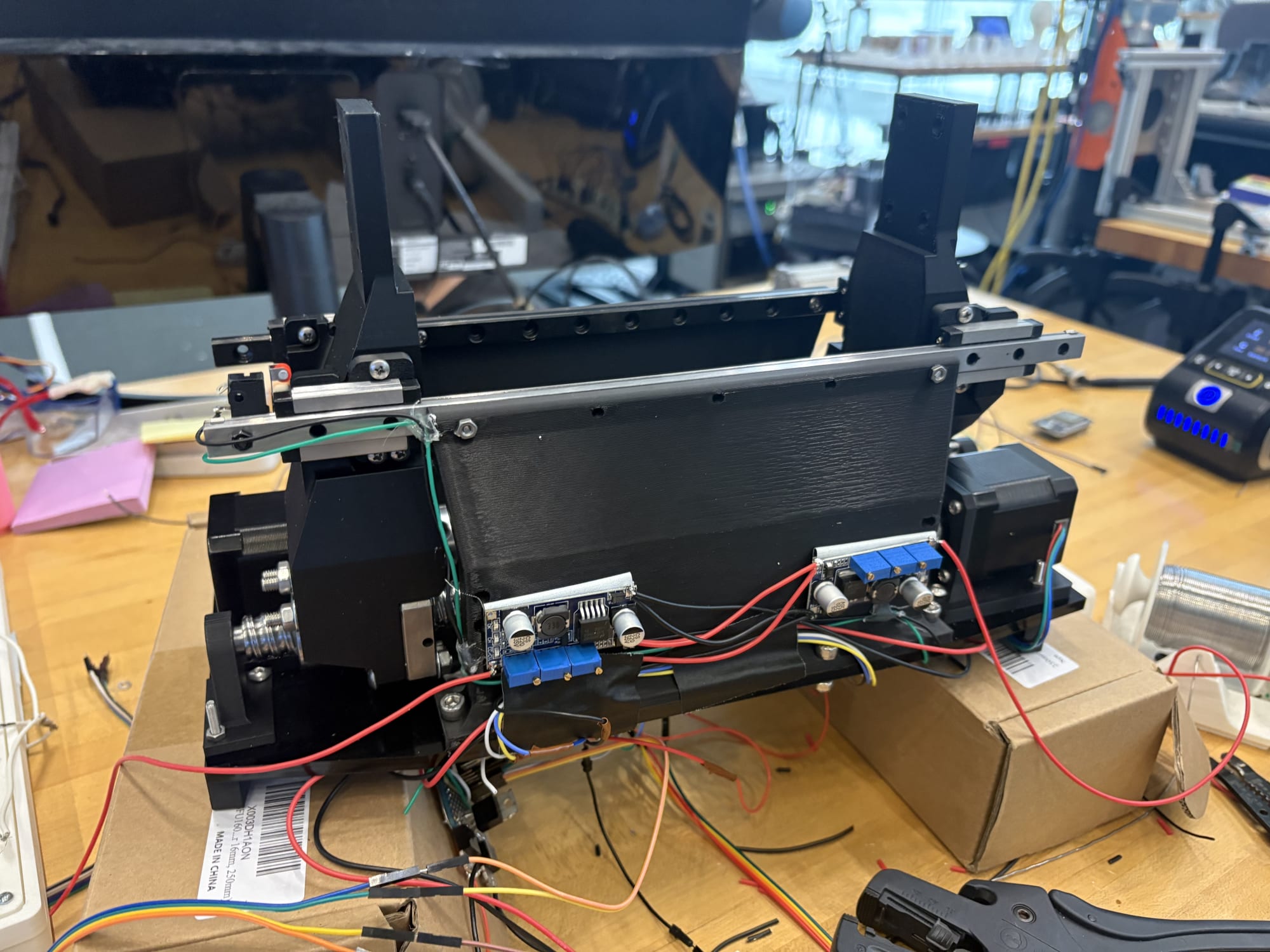 Initial ball screw design
Ball screw actuation
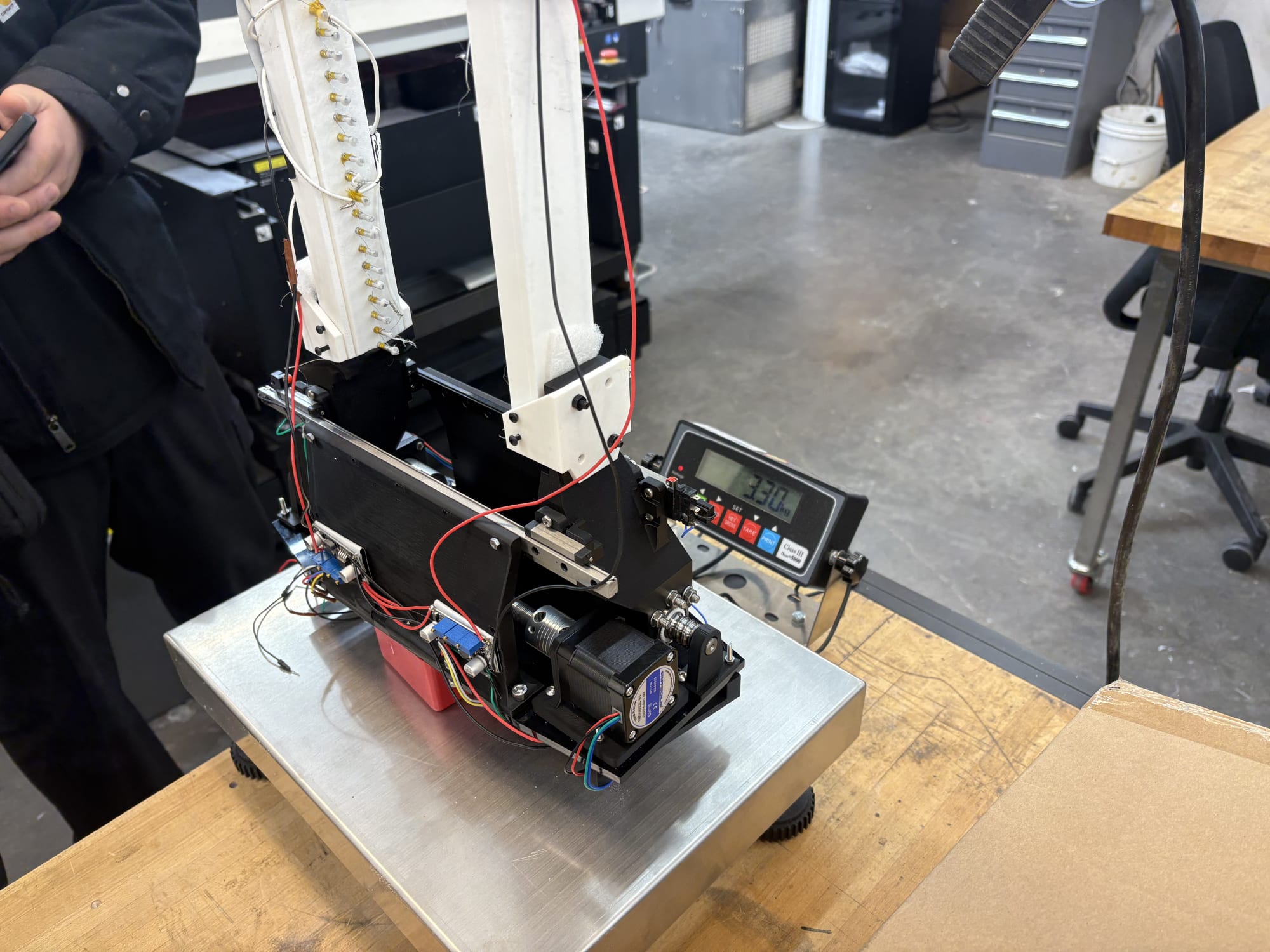 Weighing the end effector
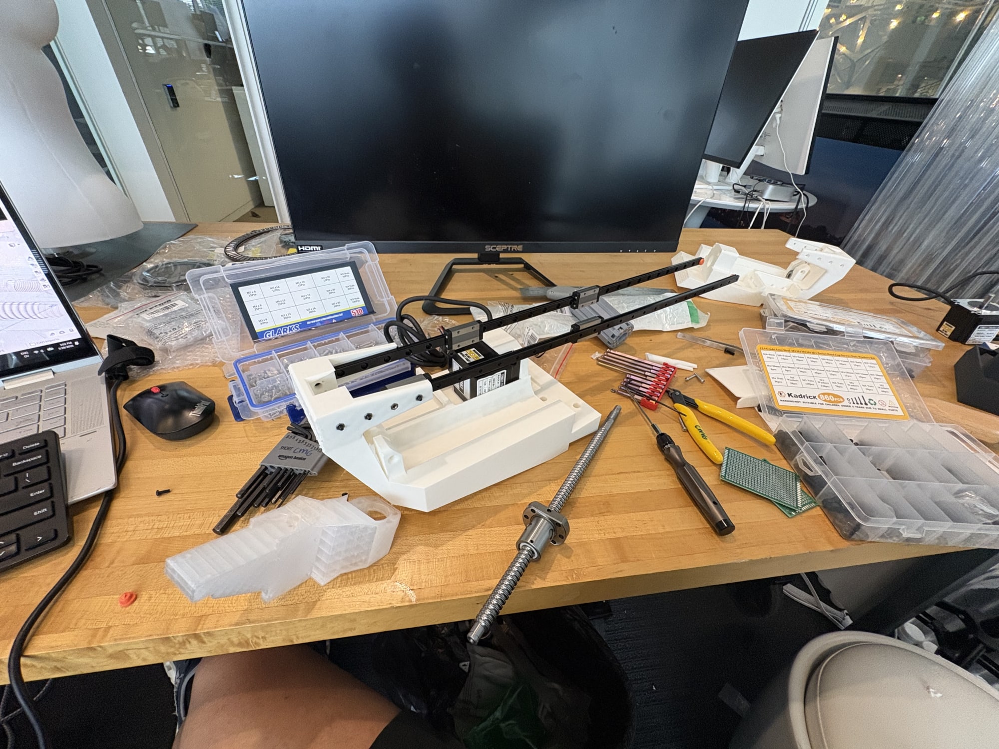 Construction of final design
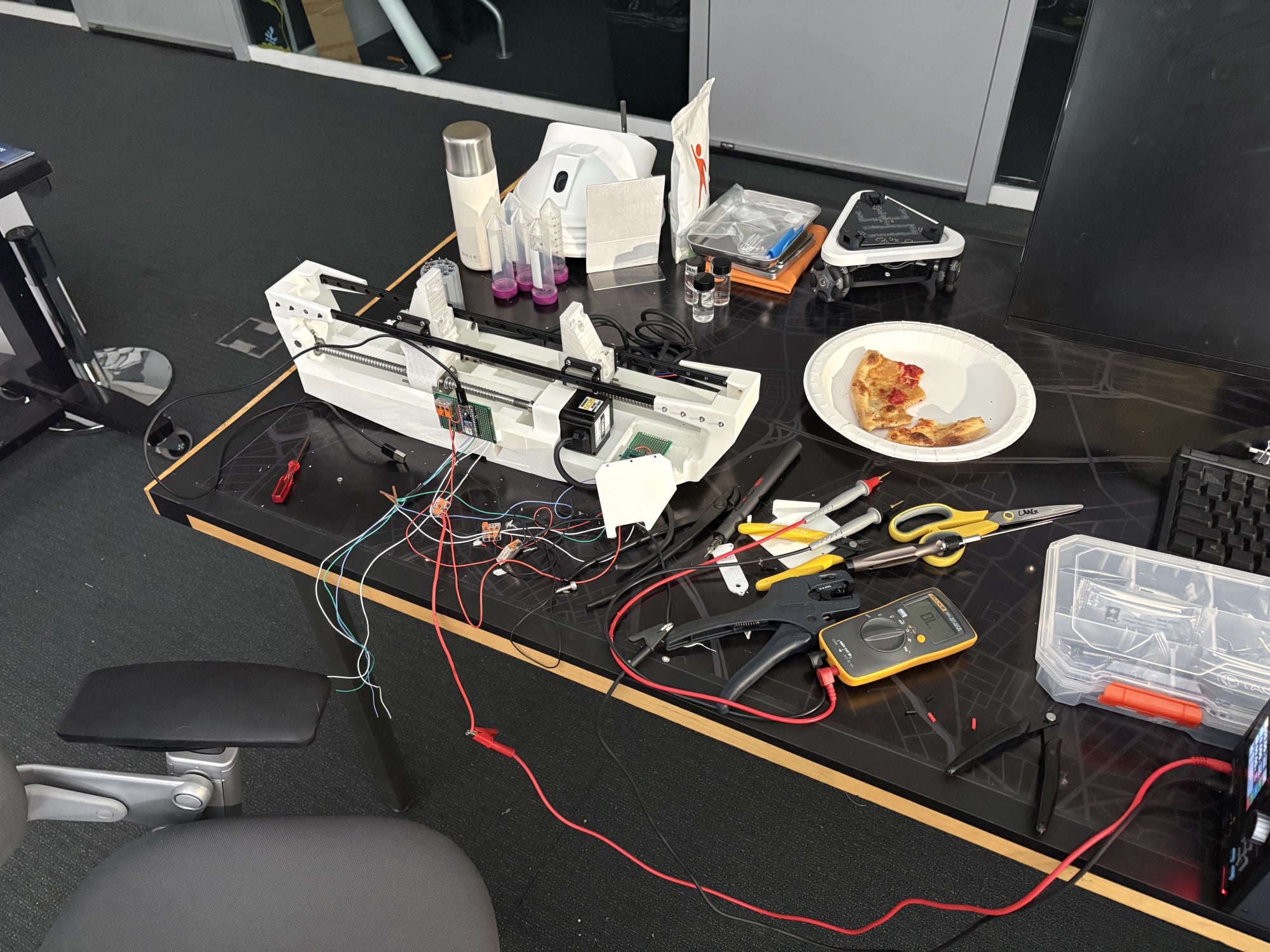 Construction of final design
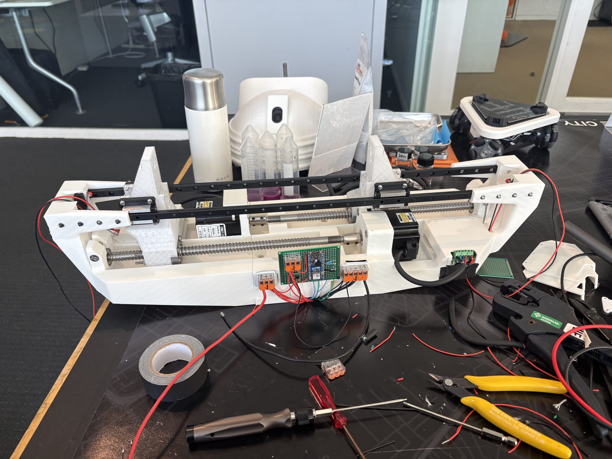 Construction of final design
Special thanks to Yuxiang Cheng, Sergio Mutis, Eleni Morales, and the entire Critical Matter team for their support!