Thrust Vector Control Rocket
In the summer of my 11th grade (2024), I set off on independently building a Thrust Vector Controlled (TVC) model rocket.
Most model rockets rely on passive stability with fins to keep their vertical orientation, pushing their center of pressure behind their center of mass. Thrust vectoring is a technique used on larger orbital or suborbital rockets that gimbals the engine to allow for active control. On the model scale, it is not commonly used, but a properly built TVC rocket will result in an incredibly stable flight, even at slow launch speeds.
I had loved rocketry throughout high school, co-founding our high school’s first rocketry club and teaching students to build and fly passive rockets to compete in TARC. I had followed Joey B’s (BPS.Space) work for quite some time, and building a TVC rocket had always been a dream of mine. In the spring of my 11th grade year, I decided to fully commit to building and launching a stable TVC rocket by the end of the summer. I was responsible for every aspect of this project, including electronics, CAD, testing, simulation, and firmware.
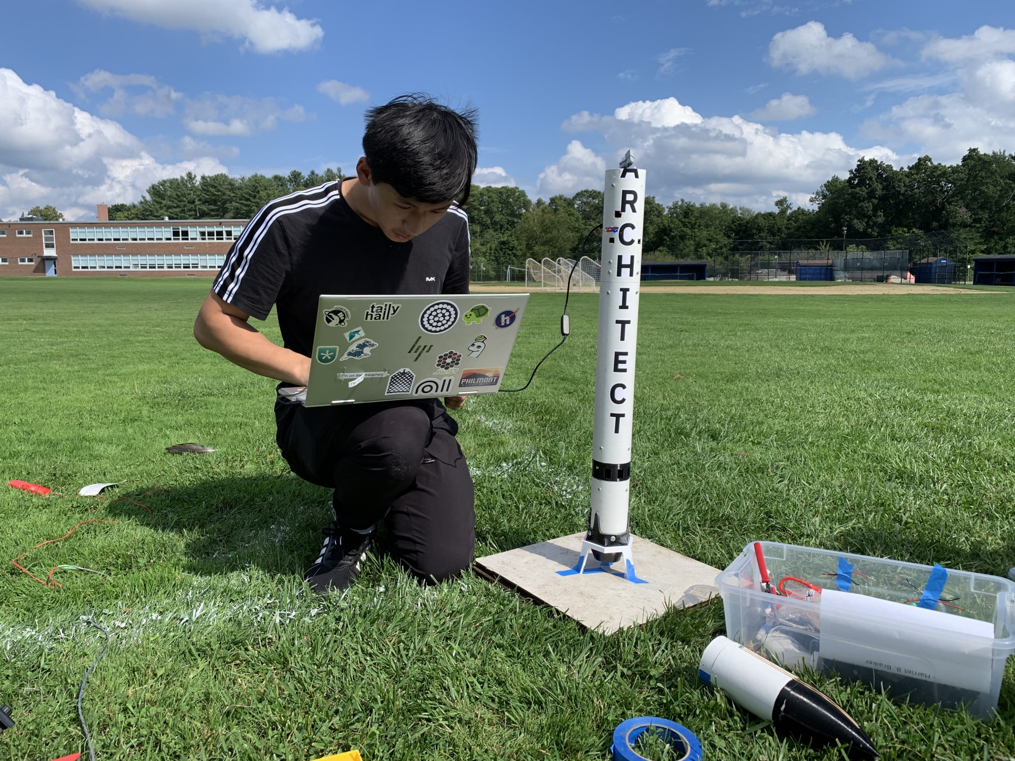 Prepping for launch
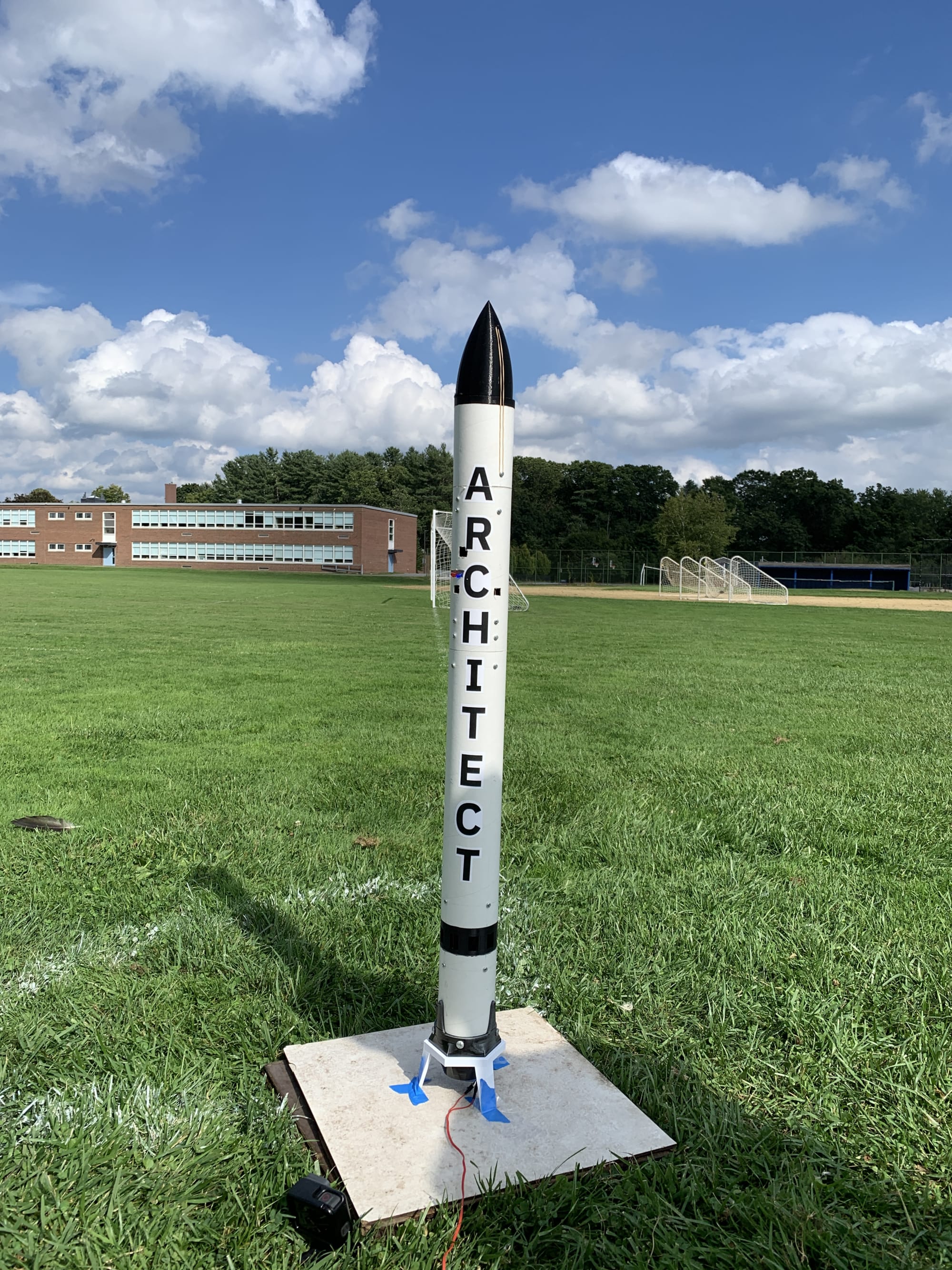 Architect!
Overview
Architect is approximately 1 meter long, 3 inches in diameter, and weighs a little over half a kilogram. Breaking it down, components include:
- A TVC mount that holds and gimbals the engine using servos
- The main airframe of the rocket
- The avionics system, responsible for sensors, active stability, and commanding servos/chutes
- A vent to divert ejection charge gases out the side
- A novel nichrome/rubberband nosecose chute ejection system
The rocket takes in gyroscope data from an IMU to get its orientation and represents it in quaternion format. This data is then used to get an offset from vertical in each its Y and Z axes (pitch and yaw). The error in each of the axes are fed into PID controllers, which send a command to the servos that gimbal the rocket motor, vectoring the thrust. A barometer estimates the altitude the rocket is at, and when apogee is detected, sends a command to heat up a strand of nichrome wire and cut a rubber band, triggering chute deploy.
TVC Mount
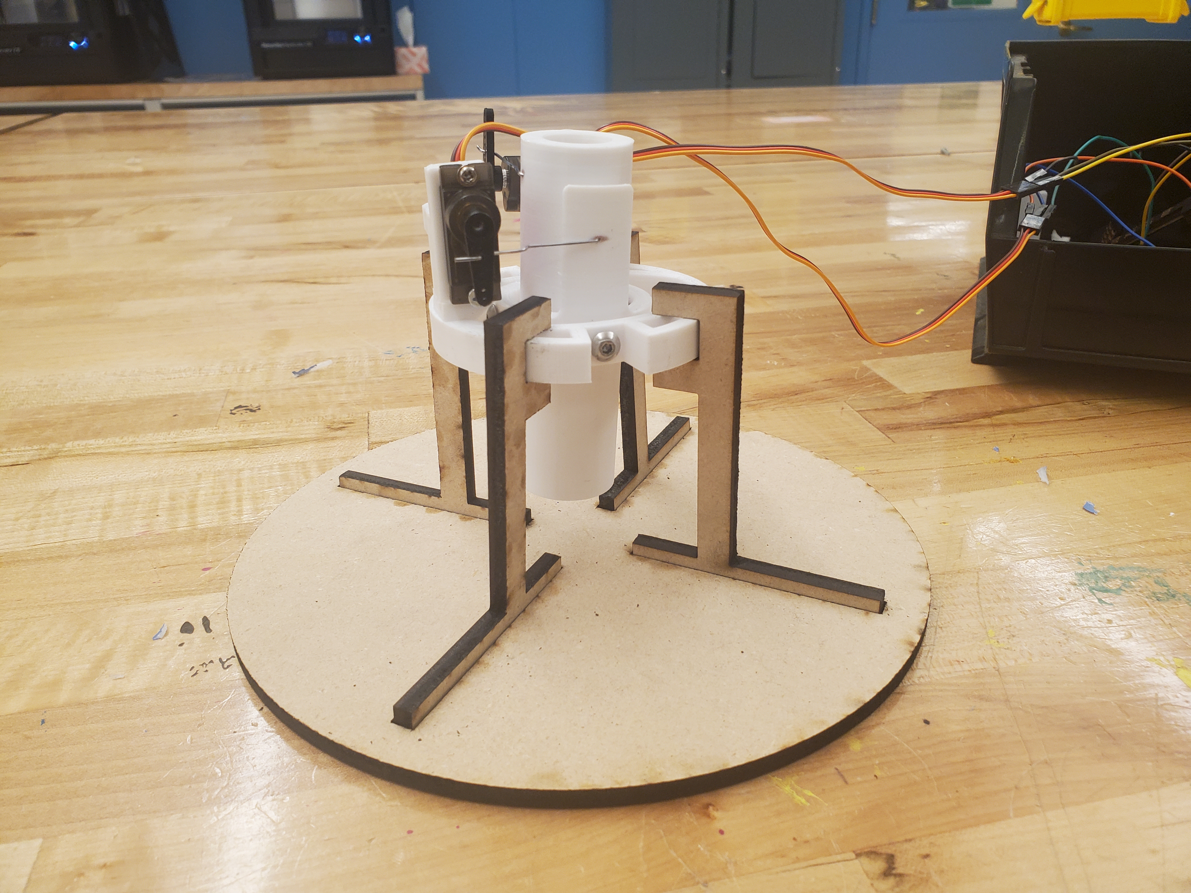
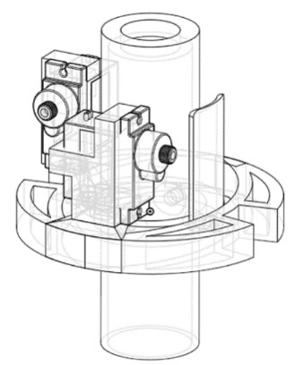
The TVC Mount serves as the main piece of hardware that enables the rocket motor to gimbal along two axes, allowing the rocket to control its pitch and yaw. The mount was initially designed in Onshape and 3D-printed using PETG. The mount allows two MG90S metal-geared servos to independently control each axes to ±5 degrees on the Z-axis, and ±7 degrees on the Y-axis.
Typically, there are two different methods used to create a TVC mount for a hobbyist thrust vector-able solid rocket motor. The first consists of a single rotation of the motor against a ball joint, with actuatable rods that run along two perpendicular axes to gimbal the motor. This design takes up less volume and mass. The second method is similar to a circular gimbal that can only actuate along two axes. Two concentric circles are allowed to rotate perpendicular to each other, and servos seated on top control the orientation of the motor. This design is heavier, albeit easier to manufacture. I chose the second design, as I wanted something to be manufacturable with only 3D-printed parts and easily-accessible screws.
I designed my mount to fit a 24mm solid rocket motor, allowing for a wide range of commercial mid-power solid rocket motors. The motor that I chose to use was the Estes E-12, with a total impulse of 28.80 Newton-seconds and an average thrust of 12 Newtons. To enable the servo motors to actuate the motors, paperclips were modified to be used as linkages to connect the servo arm to the motor gimbal.
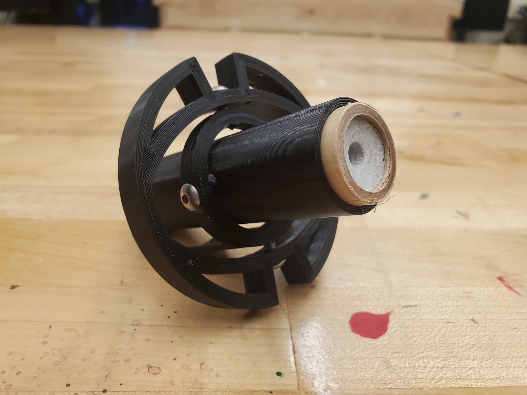 TVC Mount V1
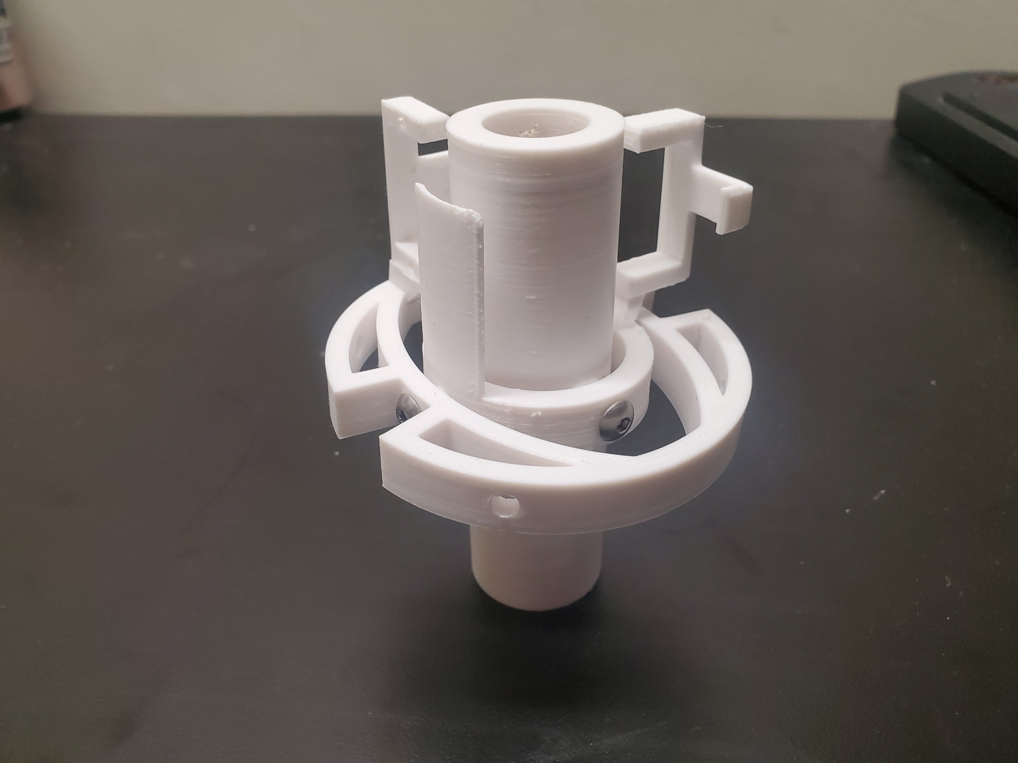 TVC Mount V2
Flight Computer
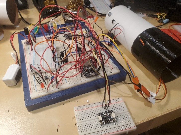
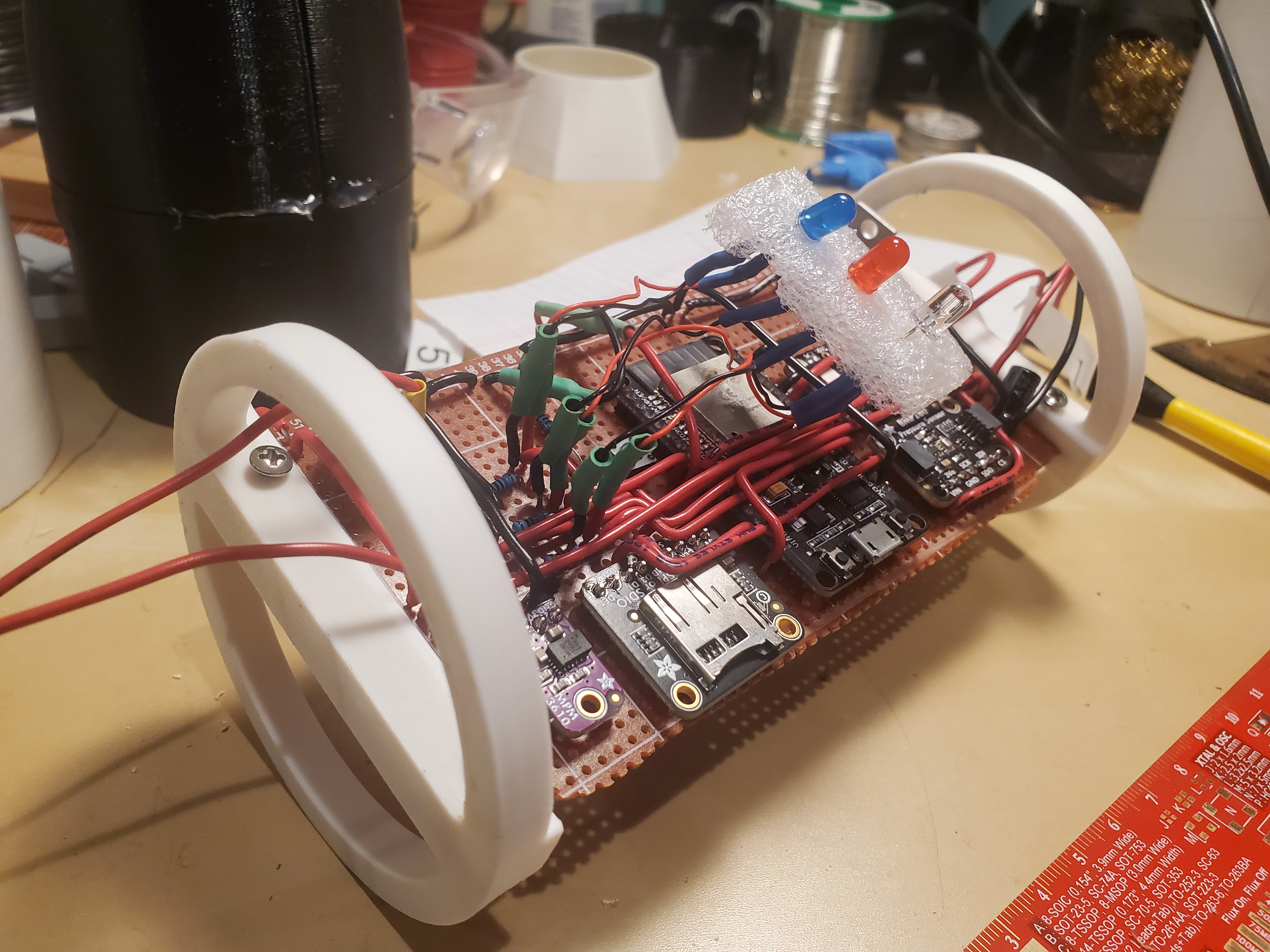
As the heart and brains of the rocket, the flight computer collects sensor data from its IMU and barometer, calculates orientation and altitude amongst other metrics, and sends commands to actuate the servos as well as deploy the parachutes. The central microcontroller used was the ESP32, chosen for its high processing speed, large amount of GPIO pins, and low cost. In this project, I chose to use several pre-built breakout boards for sensing, data logging, and power management instead of designing the entire flight computer from individual components. These breakout boards include:
- IMU: LSM6DS3TR-C
- Consists of an accelerometer and gyroscope
- Chosen for its accuracy over the MPU6050 and low cost over the BNO055
- Barometer: BMP280
- Data Logging: MicroSD Card Breakout
- Power regulation: 5V and 3.3V Buck Converters
- Status LEDs
Besides breakout boards and the main microcontroller:
- 36 gauge Nickel-Chromium (Nichrome) wire
- Serves as electronically actuated way to cut rubber bands for parachute deployment
- N-Channel power MOSFET
These systems were first tested on a breadboard to verify that I could get them working together. After verification, I soldered them on a single Perfboard to be inserted into the airframe of the rocket with 3D-printed mounts.
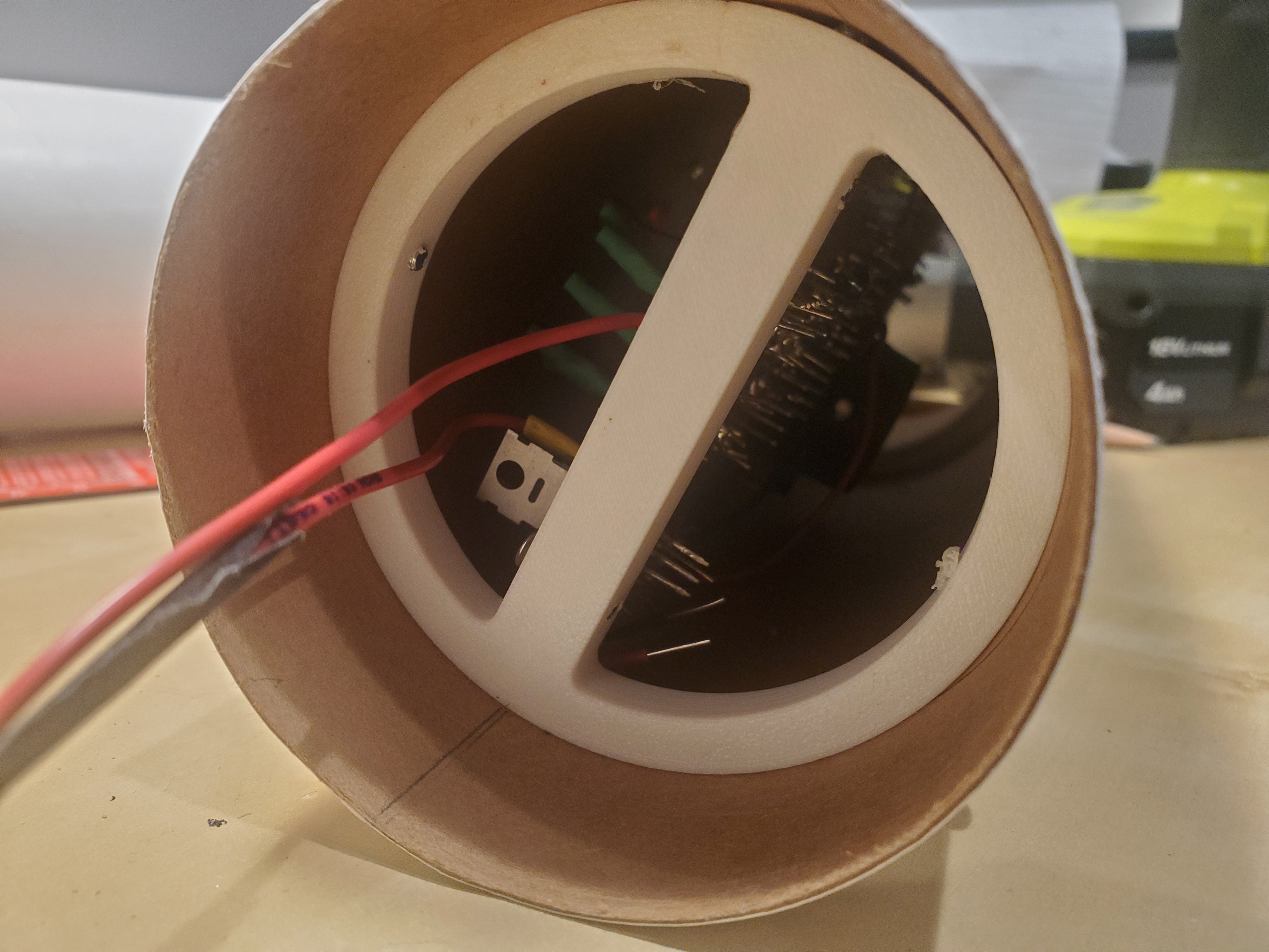
Chute Ejection
Traditional low and mid-power model rockets utilize a built-in ejection charge in its rocket motor to pressurize the airframe, pop off the nosecone, and release the parachute for recovery. This ejection charge is separated from the main burn by a delay charge, which burns for a set amount of time before the ejection charge is released.
While this may work reliably for traditional rockets, this posed a problem to the TVC rocket while I was designing it. The parachute must deploy on command in case of an abort, and the pressurization of the airframe that the ejection charge offers would expose the sensitive electronics to hot, high-pressure gases.
To solve these issues, I chose to construct a vent that would divert the ejection charge gases out of the sides of the airframe, and design a system to control the release of a parachute through cutting a rubber band with Nichrome wire.
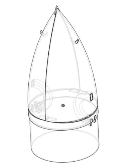 Nosecone closed
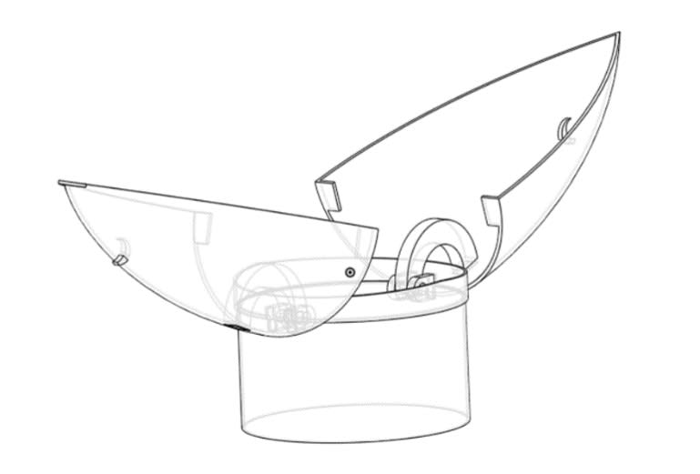 Nosecone open
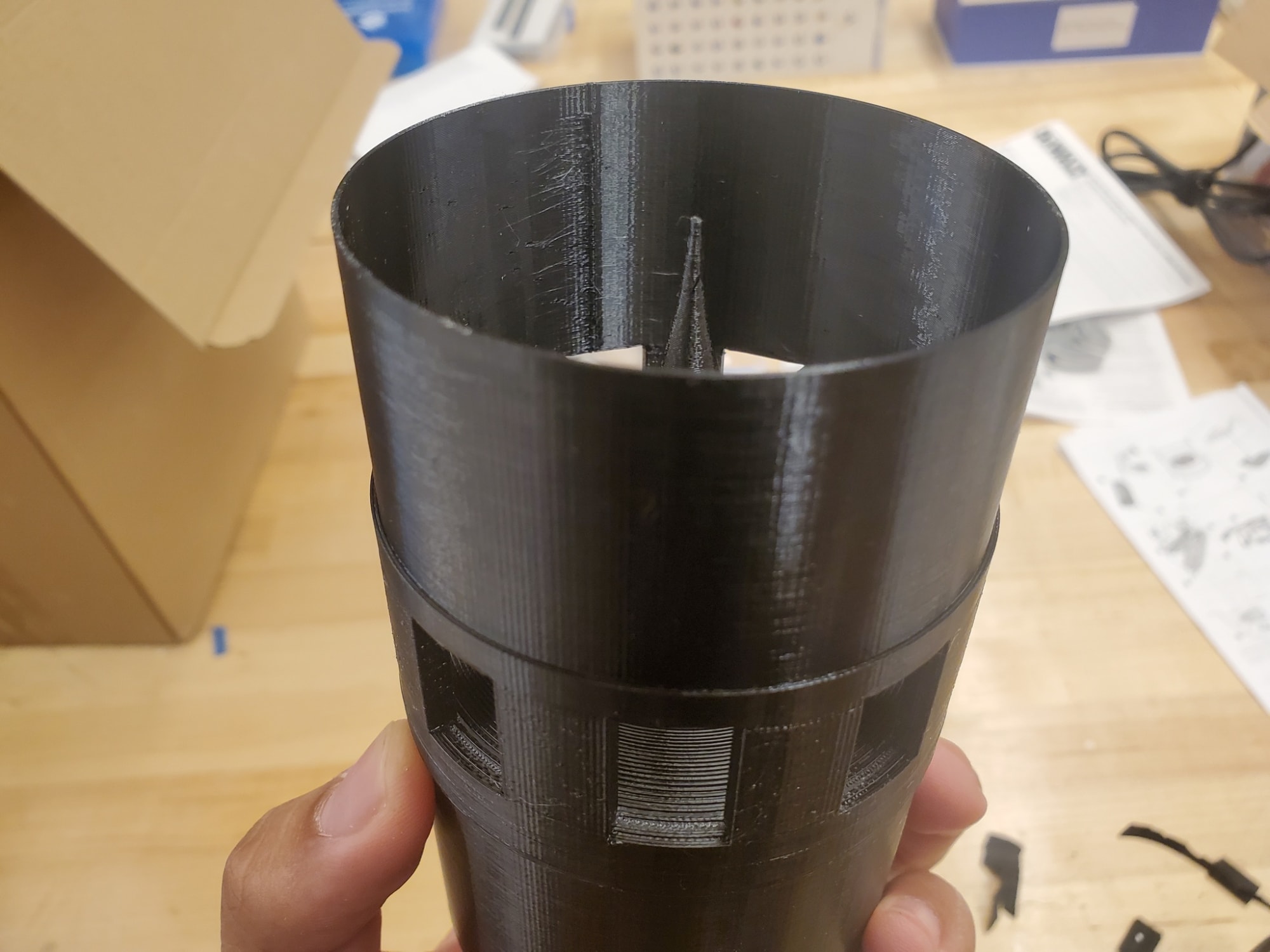 Ejection charge divert vent…
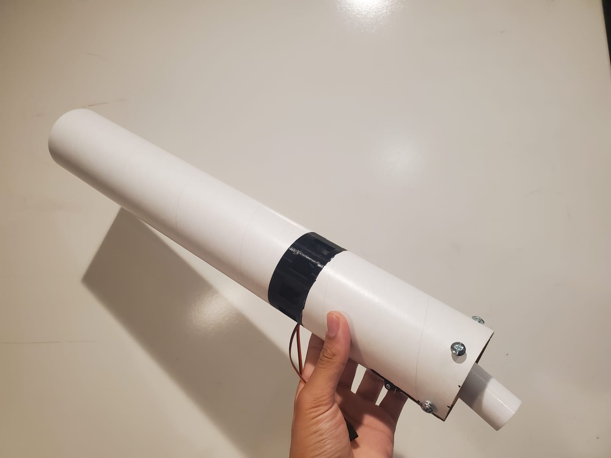 …integrated into the aft end
Software/Firmware
Quaternions
This rocket uses a quaternion-based approach to calculating and updating its orientation strictly from gyroscope measurements of the IMU. Typically, when an IMU is used to calculate orientation, sensor fusion and filtering is used to take measurements from both the accelerometer and gyroscope to produce a more accurate reading of the device’s orientation. However, under high-acceleration environments, such as that of a model rocket, methods that use accelerometer readings may fail to give accurate orientation data. This is why gyroscope-only-based approaches are commonly used among TVC hobbyists. While more susceptible to drift in the long run, in a short flight, the data given by the gyroscope is sufficiently accurate.
There are three common ways to represent the orientation (attitude) of an object. Those three are through Euler angles, rotation matrices, and quaternions. Euler angles and rotation matrices fall flat as they are both susceptible to gimbal lock and rotation matrices can be computationally expensive. As quaternions are often the representation of choice in industry, I chose to go with them.
Quaternions, at its base, are represented as an extension of complex numbers. While traditional complex numbers are in the form \(a + bi\), quaternions are in the form \(w + xi + yj + zk\), where \(i\), \(j\), and \(k\) are all complex numbers. When defining rotation, many parallels can be drawn between quaternions and angle-axis rotation. The real part \(w\) can represent the angle rotated around the axis, and the coefficients \(x\), \(y\), and \(z\) represent the axis in 3D space. The rotation quaternion can be constructed as:
\[q = \cos(\theta) + \sin(\theta)(xi + yj + zk)\]As we are given the angular velocities \(\omega_x\), \(\omega_y\), and \(\omega_z\) we can determine the axis of rotation, as well as the angle rotated for a measured \(dt\).
Using the formula \(q' = qvq^{-1}\), where \(v\) is a quaternion representing the initial orientation of the rocket (in my case, \(j\)), we can construct a final equation that allows us to determine the current orientation \(q\) based on multiple small rotations \(q_0 ...q_n\):
\[q=(q_0 \cdot q_1 \cdot q_2 \cdot ... \cdot q_n) (0 + 0i + j + 0k)(q_0 \cdot q_1 \cdot q_2 \cdot ... \cdot q_n)^{-1}\]Now that we know our current orientation, this allows us to determine the offset from the rocket’s launch position, which gets translated into the error term fed into the PID controller.
PID Controller and Simulation
A PID (Proportional, Integral, Derivative) controller was used to ensure the rocket’s stability in flight. The PID controller uses the current orientation data and compares it to the original orientation on the launch mount. For each axis, the error between the desired and actual orientation is fed through the controller and the output is given as a torque in Newton-meters, which is turned into an angle and commanded to the servos.
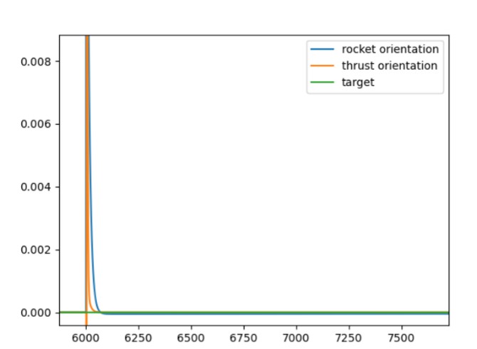
To tune the three different gains (\(K_p, K_i, K_d\)) of the PID controller, I programmed a double-integrator simulation of my system in Python and added a PID controller to control orientation. As no air resistance is assumed and the position of the rocket is not important, this simulation only considered the torques acting upon the rocket that rotate it around its center of mass.
In total, the simulation factors in the frequency of the microcontroller loop while in flight (~\(21Hz\)), the delay between the servo actuation command and real actuation (~\(33ms\)), the mass moment of inertia of the rocket, the mass of the rocket, the thrust of the rocket motor, and the distance between the rocket’s center of mass to the TVC mount’s pivot point. After manually tuning the PID controller, I got values that seemed optimal.
Ground Testing, Measurements, and Miscellaneous
TVC Mount Alignment
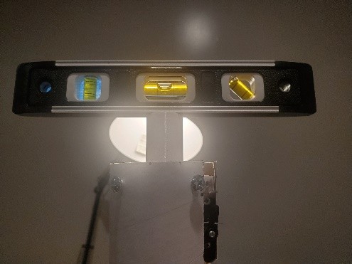
Because I did not have another IMU to spare and deemed that absolute accuracy was not necessary, aligning the TVC mount was done using a level and adjusting the servo angles from my computer.
Static Fire Test
An outdoor static fire test was performed in order to ensure that the TVC mount could withstand the force of the motor while still being able to actuate to different angles. I used Estes D-12 solid rocket motors as they were slightly cheaper yet had the same average thrust as the Estes E-12 motors. The TVC mount was placed upside down on a test stand and fired twice for 2 tests, all while alternating actuations on each axis.
Apogee Detection Tests
Apogee detection tests were also performed to ensure that the barometer could detect the highest point of its flight to release parachutes. These tests comprised of taking the avionics bay inside the airframe, taping shut the ends to simulate the closed ends of the actual rocket, and tossing it in the air. I programmed the buzzer to emit a beeping sound when apogee was detected. While I had to tweak some of the barometer’s filtering, sampling, and standby time, as well as my own moving-average filter, I eventually was able to get the flight computer to detect apogee within 1 second of reaching apogee.
Servo Delay Test
A servo delay test was performed to characterize the delay between the time the command was sent to the servo, and the time the servo actually moves. Usually, this is on the order of tens of milliseconds, but as the controller loop functions faster than that, it is important to characterize this in the simulation. To do so, I sent a command to an LED as well as the servo at practically the same time, and video-recorded the event. I later went back frame-by-frame to find the difference in time, which turned out to be 2 frames at 60fps (~33ms).
Defining a Relationship between Servo Command and TVC Mount Angle
While the PID controller outputs torque, which can be translated into a desired thrust angle, it was not clear how to command that thrust angle to the servo. Servos work by sending pulse widths, which cause them to actuate to a specific position. While the servo library I used could command a servo angle, I needed to map my commanded servo angle to the mount’s actuated angle in relation to the rocket.
To do so, I took a recording of the TVC mount from each axis and commanded the servo to actuate along that axis, reaching 15 evenly distributed positions each corresponding to 15 different servo commands along its range of motion. I then used an angle-measuring app to determine the angle of each actuation.
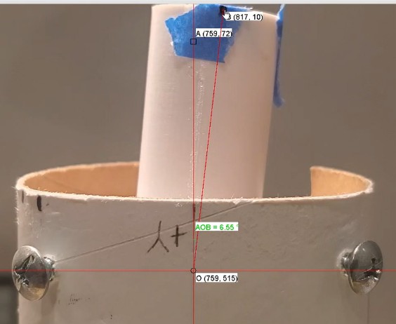
I then plotted the actuated angle against the servo command to determine a relationship between them.
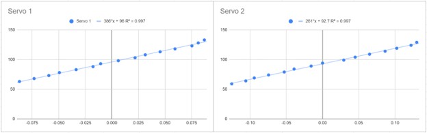
The relationship between them turned out to be very linear, surprising because I assumed that a servo actuation closer to the limits of its range of motion would have less of an effect on the TVC mount. Now that I had a function with an input of the TVC angle and an output of the servo command, I could substitute the desired angle and receive the command for the servo.
Measuring MMOI
A bifilar pendulum test was conducted to measure the mass moment of inertia of the rocket. With 2 strings of the same length suspending the rocket off the ground, the rocket was perturbed, and the period of its oscillation was measured by recording the time for 10 oscillations and dividing by 10. After repeating this trial 2 more times and finding the average period of oscillation, the equation
\[I = \frac{MgT^2 b^2}{4 \pi^2 L}\]is used to find the mass moment of inertia \(I\), given the mass \(M\), period of oscillation \(T\), length between the string’s attachment point and the rocket’s center of gravity \(b\), and the length between the table and the rocket’s center of gravity \(L\).
Aft Guard, Launch Mount and Integration!
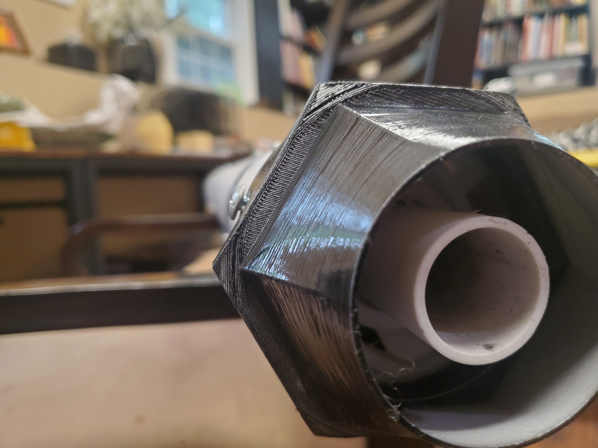
Finally, an aft guard and launch mount were both designed in Onshape and 3D-printed for the rocket. The aft guard served as a reinforcement to the cardboard tubes at the aft end of the rocket, and also served as protection for the TVC mount. The aft guard also provides a seat for the rocket to fit into the launch mount.
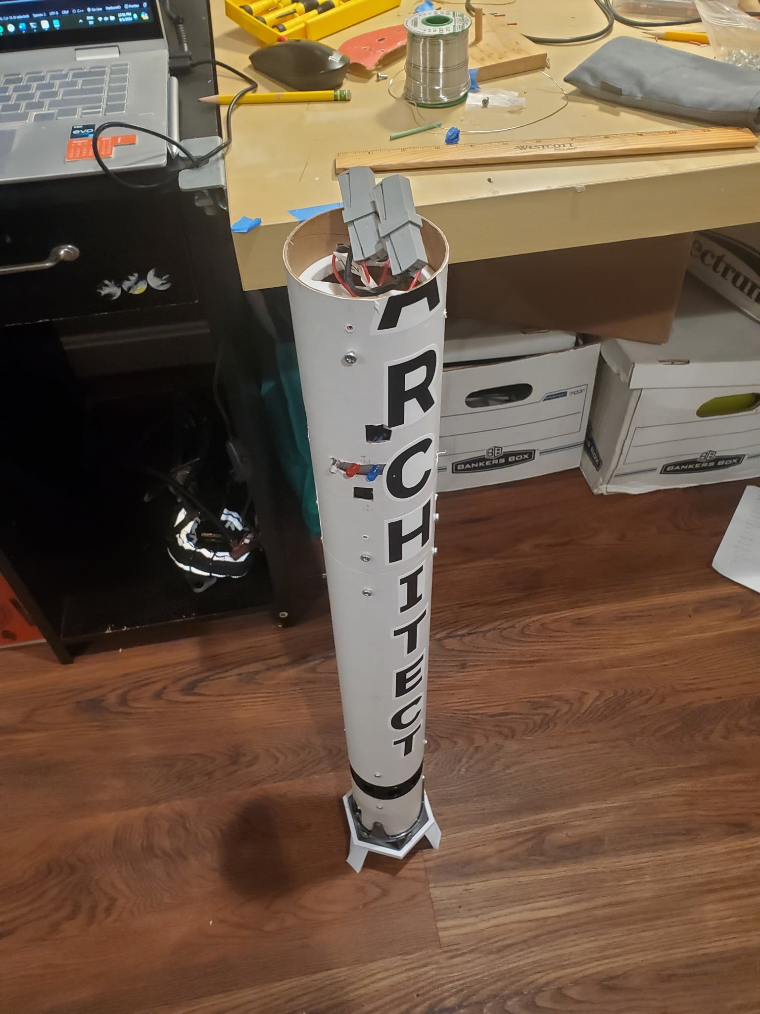 Vertical stack
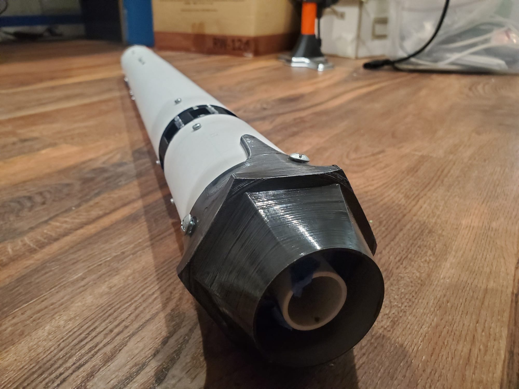 Aft end oh yeah
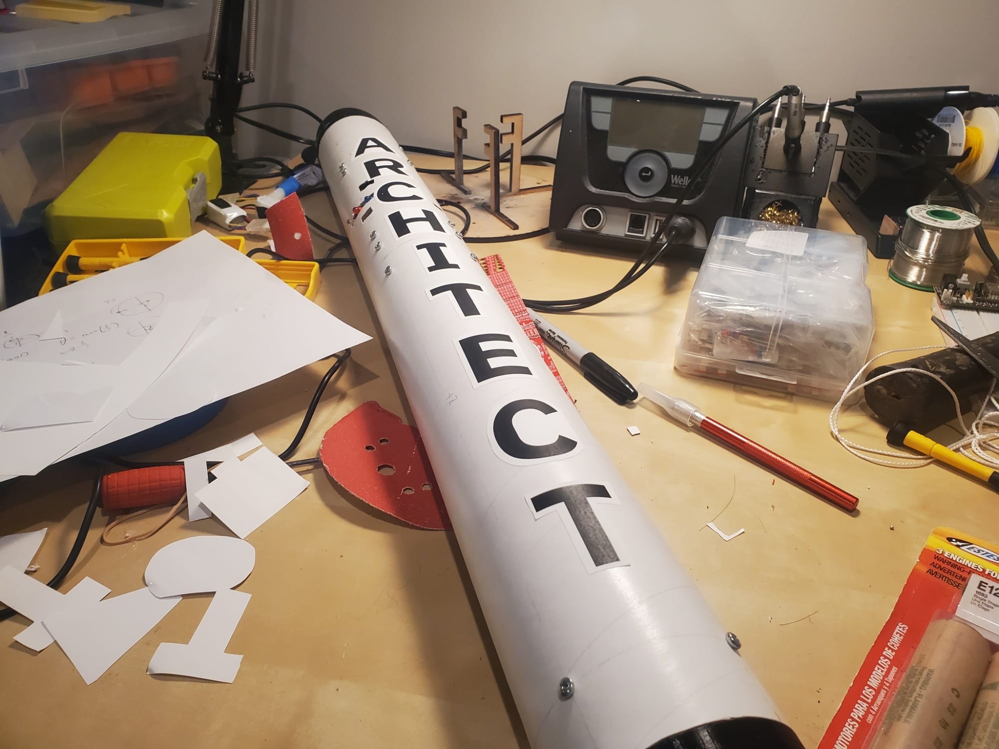 On da table
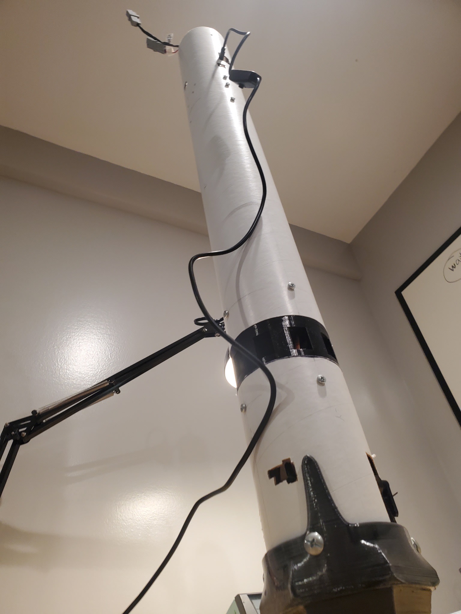 Sensor testing!
Launch!
After running through many ground tests, I finally set off to launch my rocket for its maiden flight. In the process for launch:
- The rocket starts an automatic 26-second countdown, and in the last 3 seconds, sets its current orientation as the orientation it is targeting
- Once the countdown hits 0, the rocket waits for a spike in acceleration, and a manually-controlled launch controller ignites the engine
- Once the rocket detects an acceleration spike, it switches to its inflight state, turns on the PID controller, and starts actively gimballing the motor to ensure stability
- Once apogee is detected or the orientation exceeds 50 degrees, it heats up the Nichrome wire and releases the parachutes.
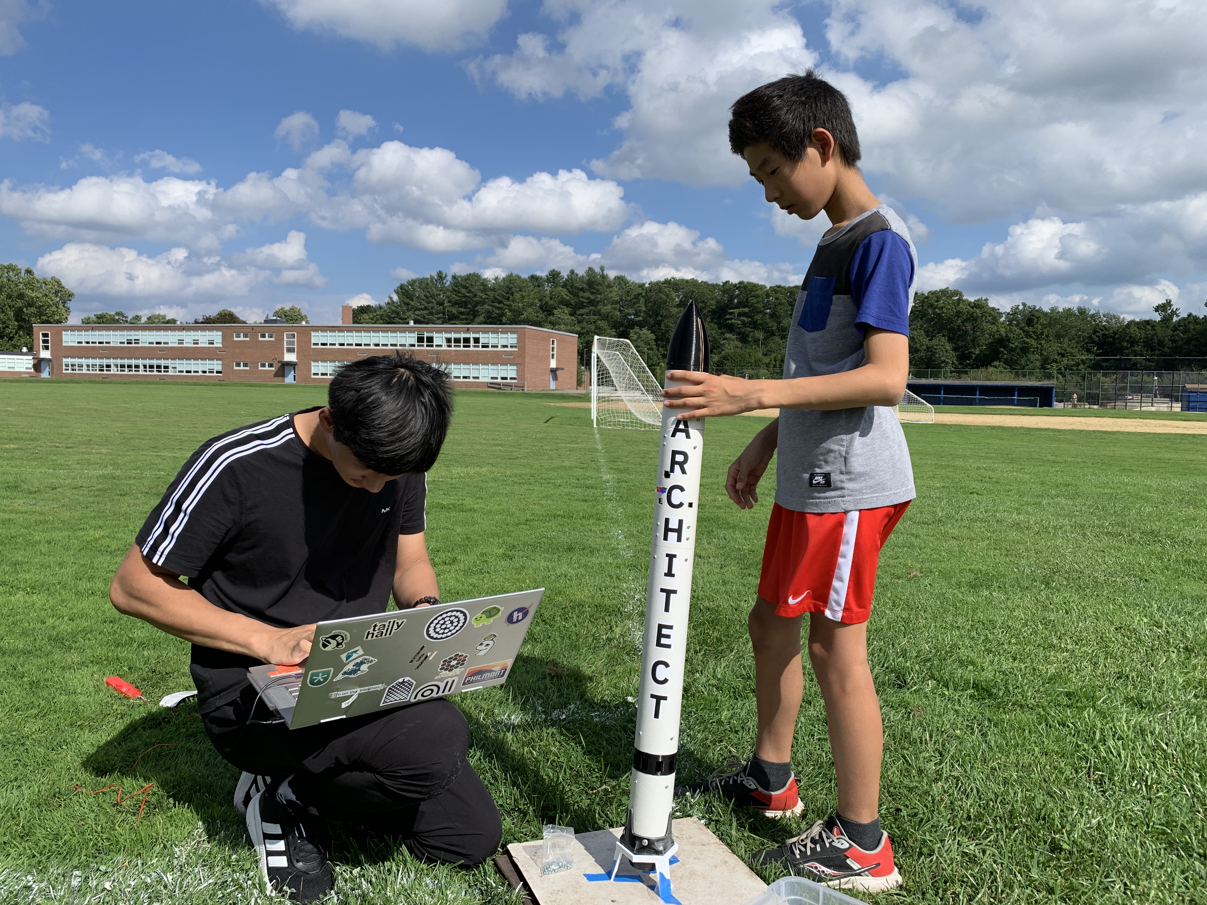
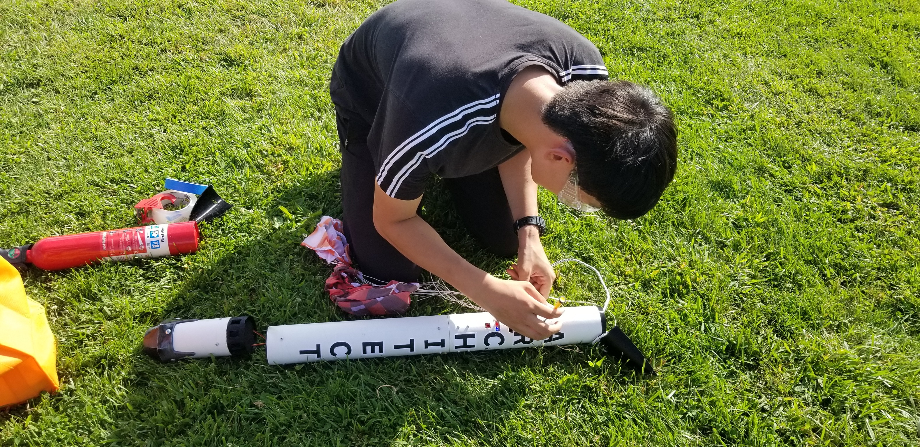
The first attempt resulted in an ignitor failure with the launch controller when the rocket was waiting for an acceleration spike. A few moments later, the wind tipped over the rocket, which caused an acceleration spike, a decrease in altitude, and an orientation of more than 50 degrees. One of the latter two factors tripped the apogee detection logic, releasing the chutes on the ground. However, resetting the nosecone was not a lengthy procedure, and the rocket was soon back on the pad.
The next test flight was a success!
Unfortunately, data was not able to be collected on the rocket’s maiden flight. In retrieving the rocket, I mistakenly reset the microcontroller to ensure that the rocket was safed, but it also overrode all data logged onto the MicroSD card.
Conclusion
This project was by far, the most fun project I had undertaken in high school. The process from inspiration to design to construction to a successful test is extremely rewarding, and I learned so much about control theory, CAD, testing, electronics, and managing a project. I’m so grateful for everyone who has supported me along the way, including my friends, family, makerspace mentors, the Big Blue Boom Crew (our rocketry club), and r/AmateurTVC.